
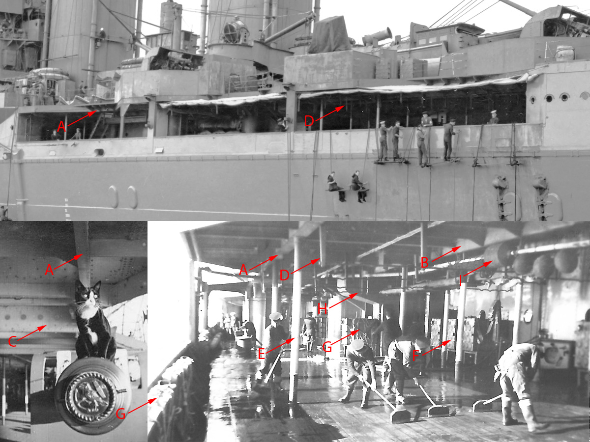
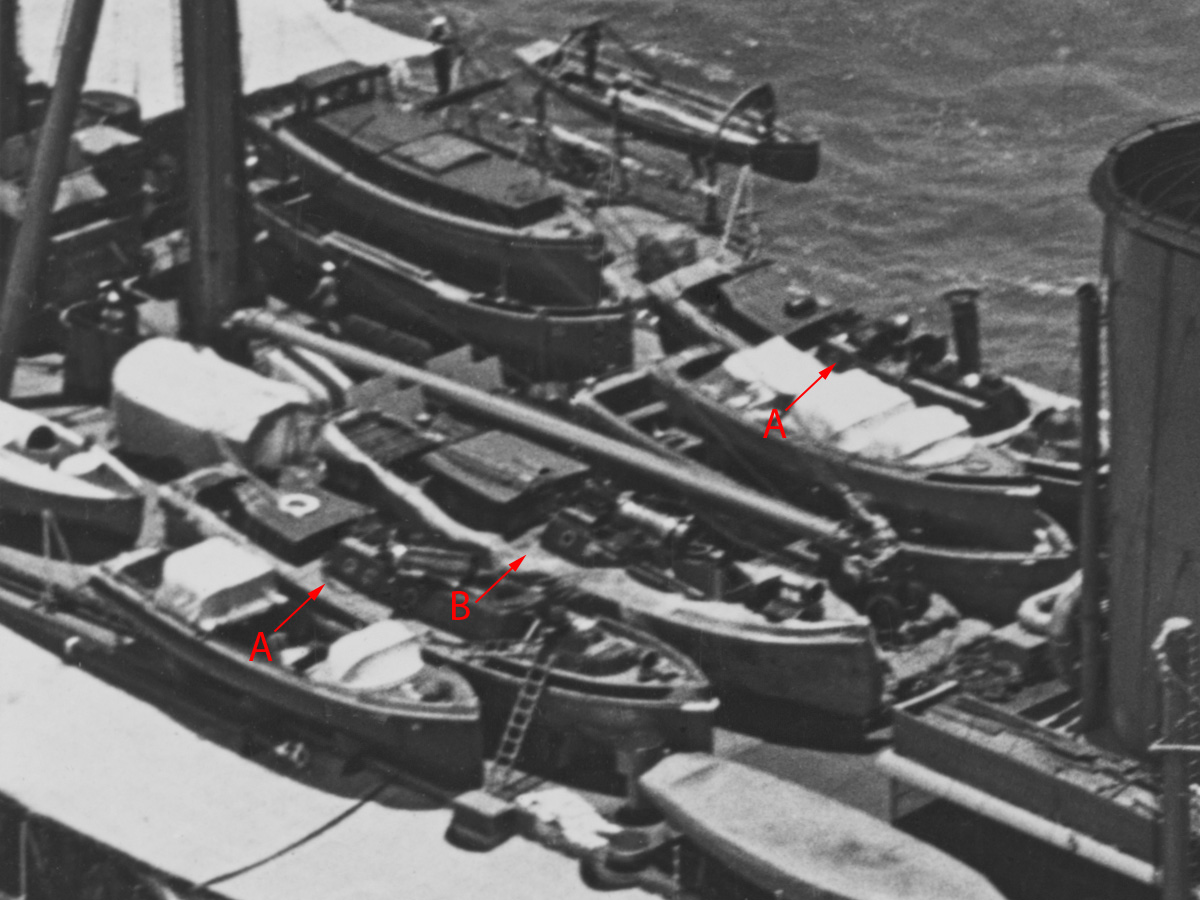
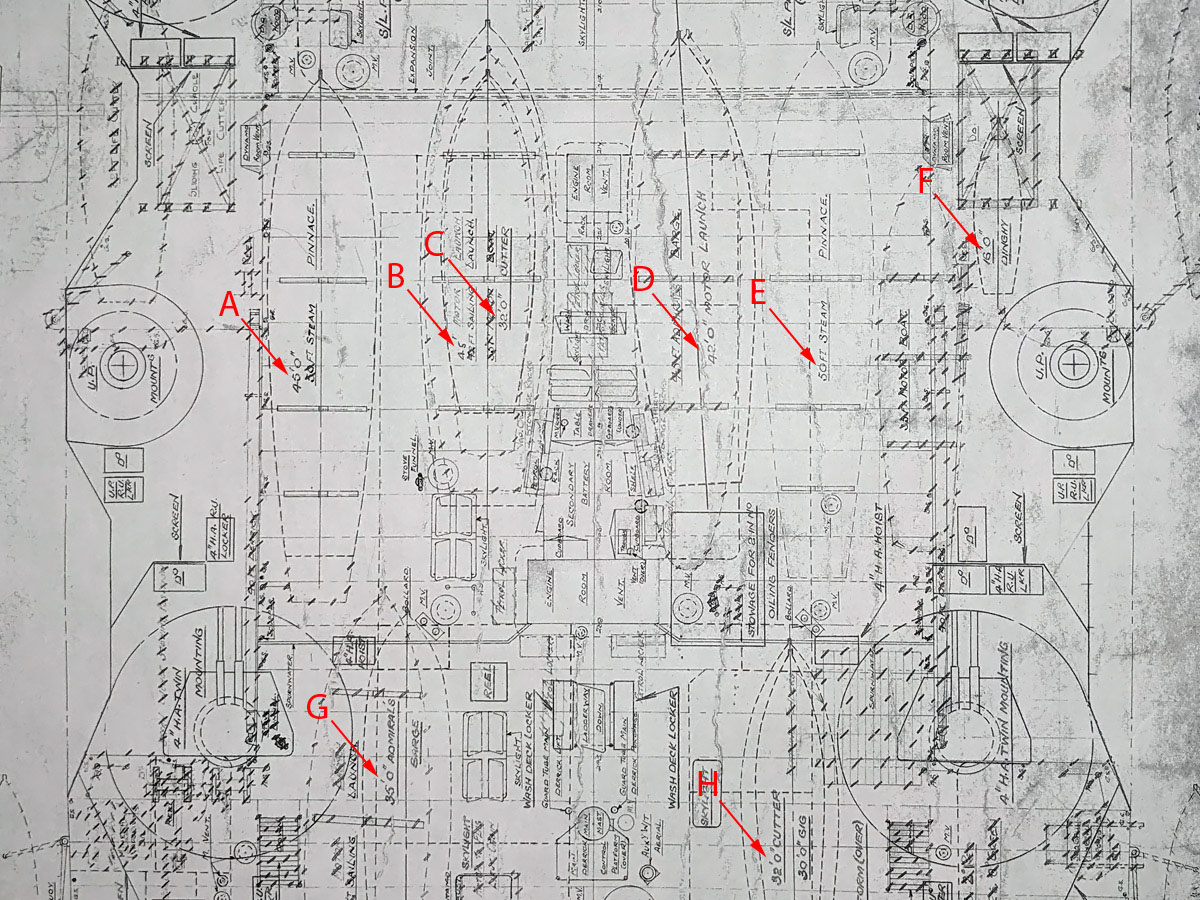
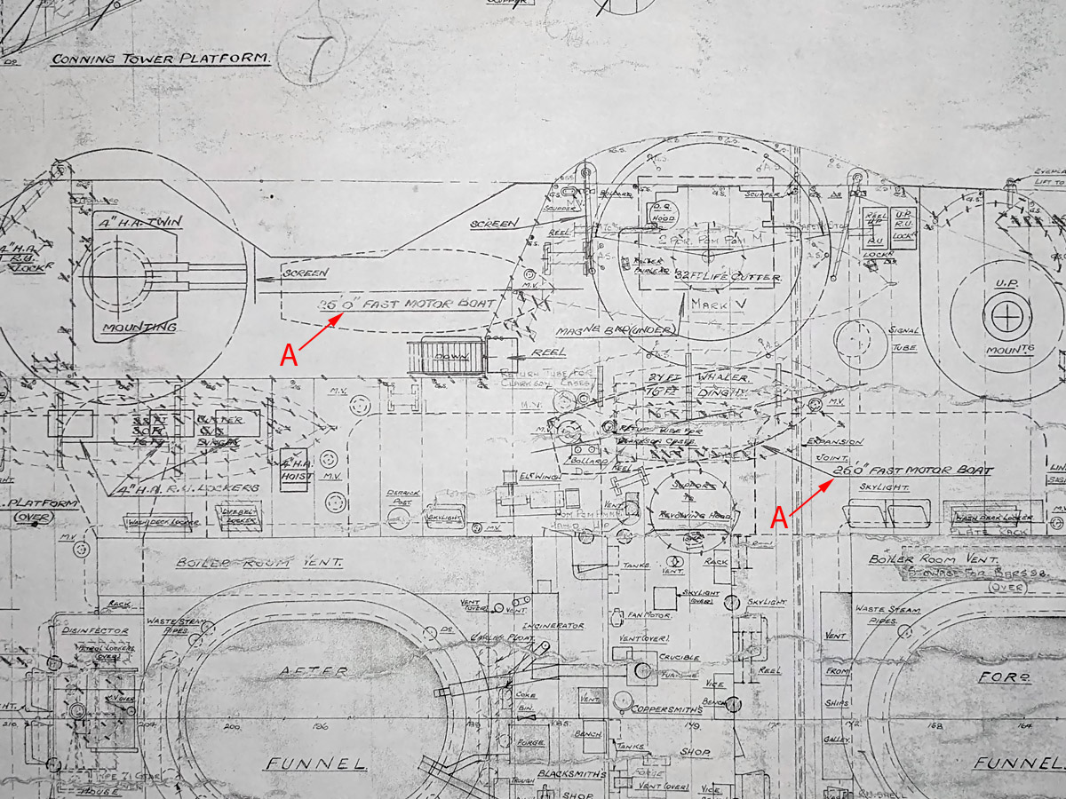
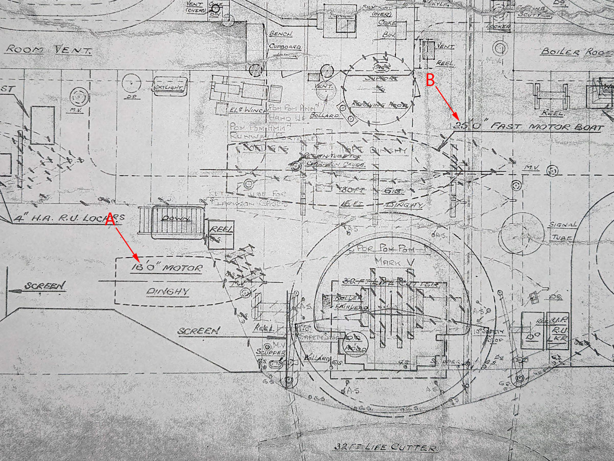
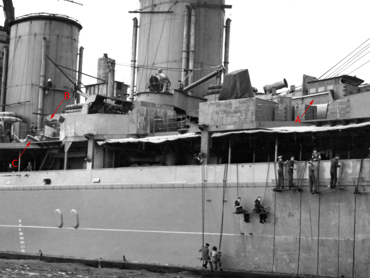
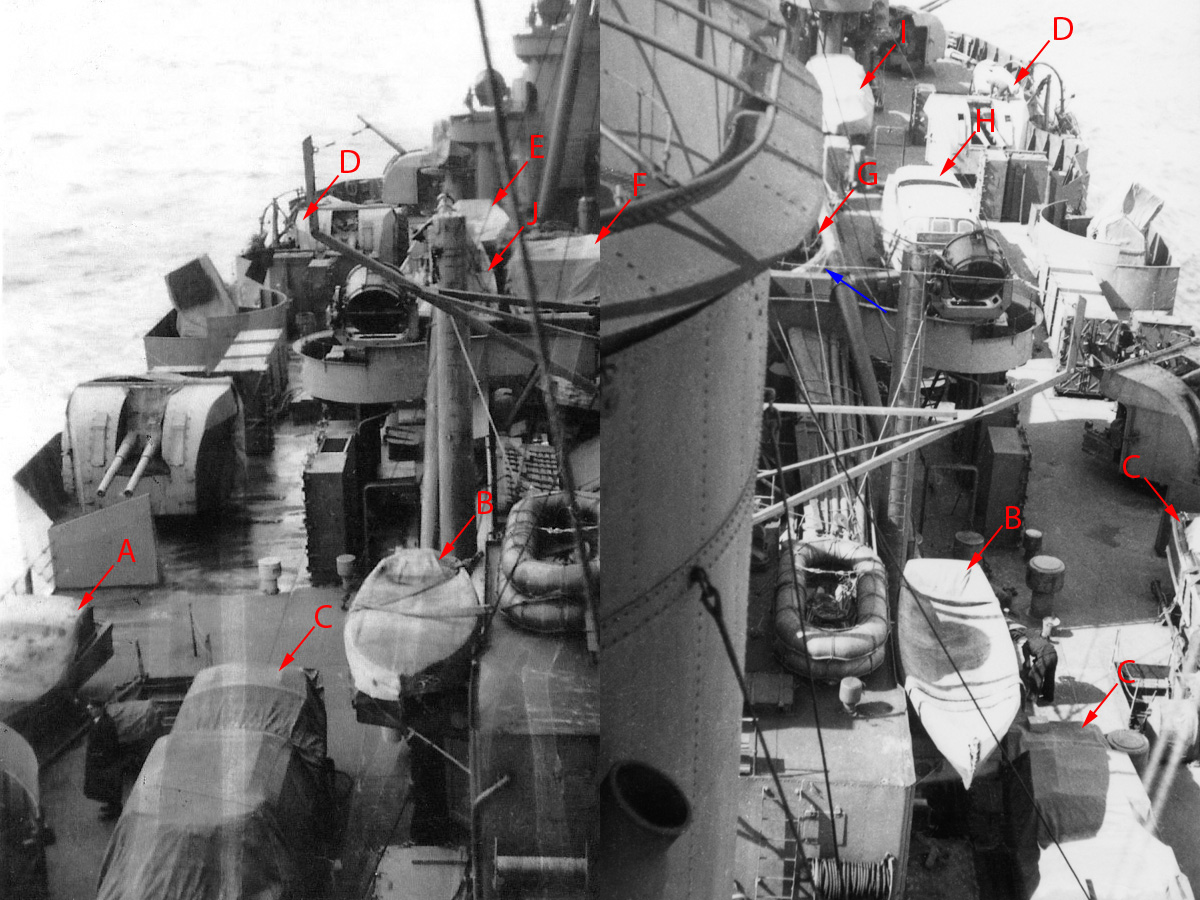
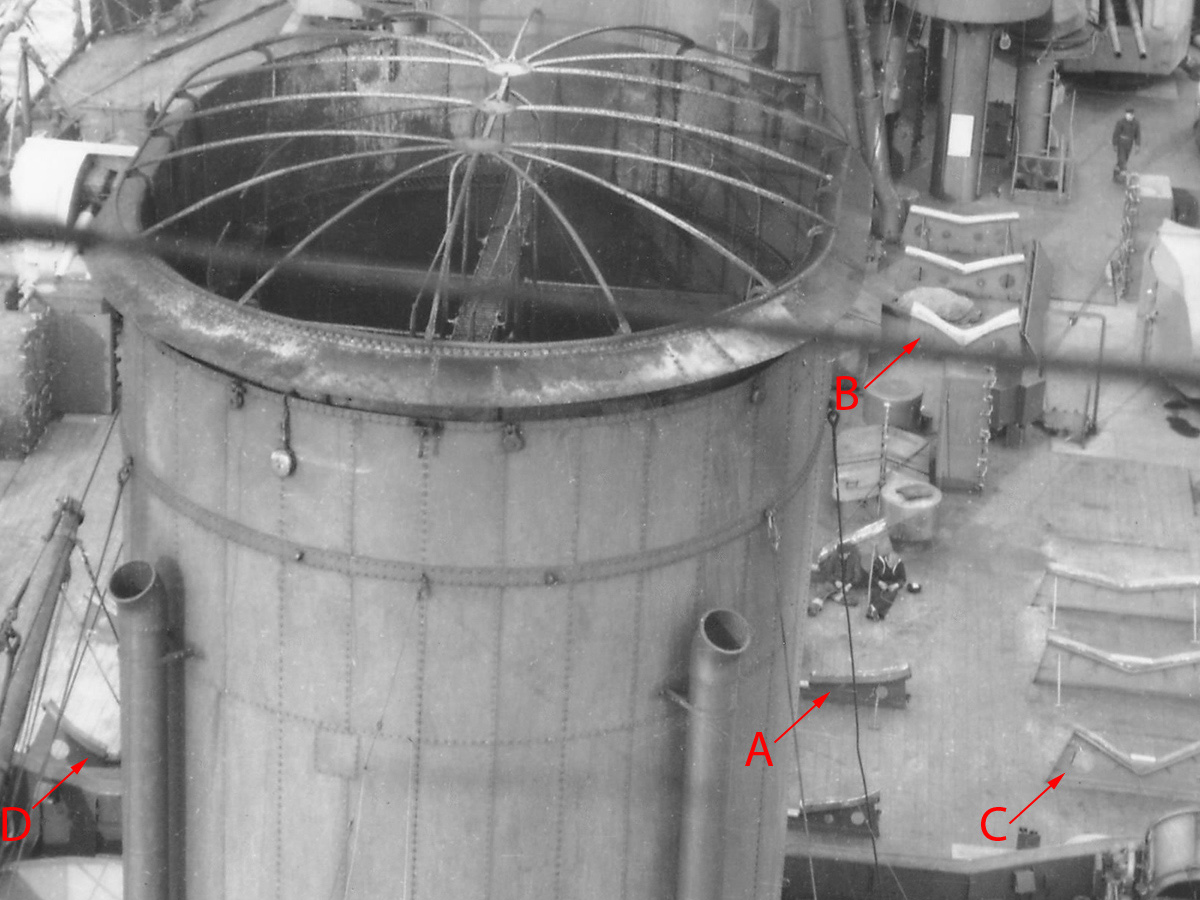
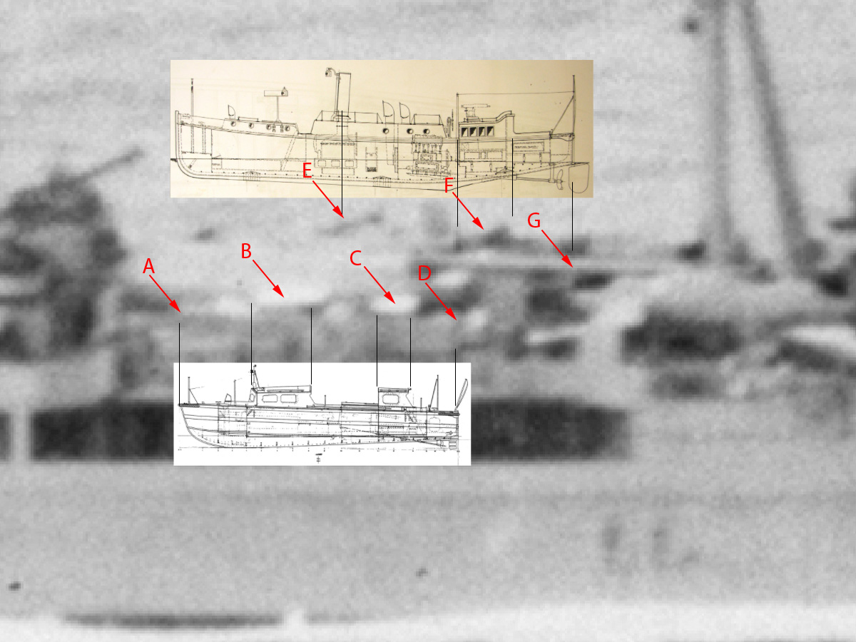
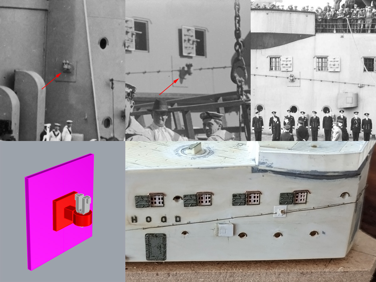
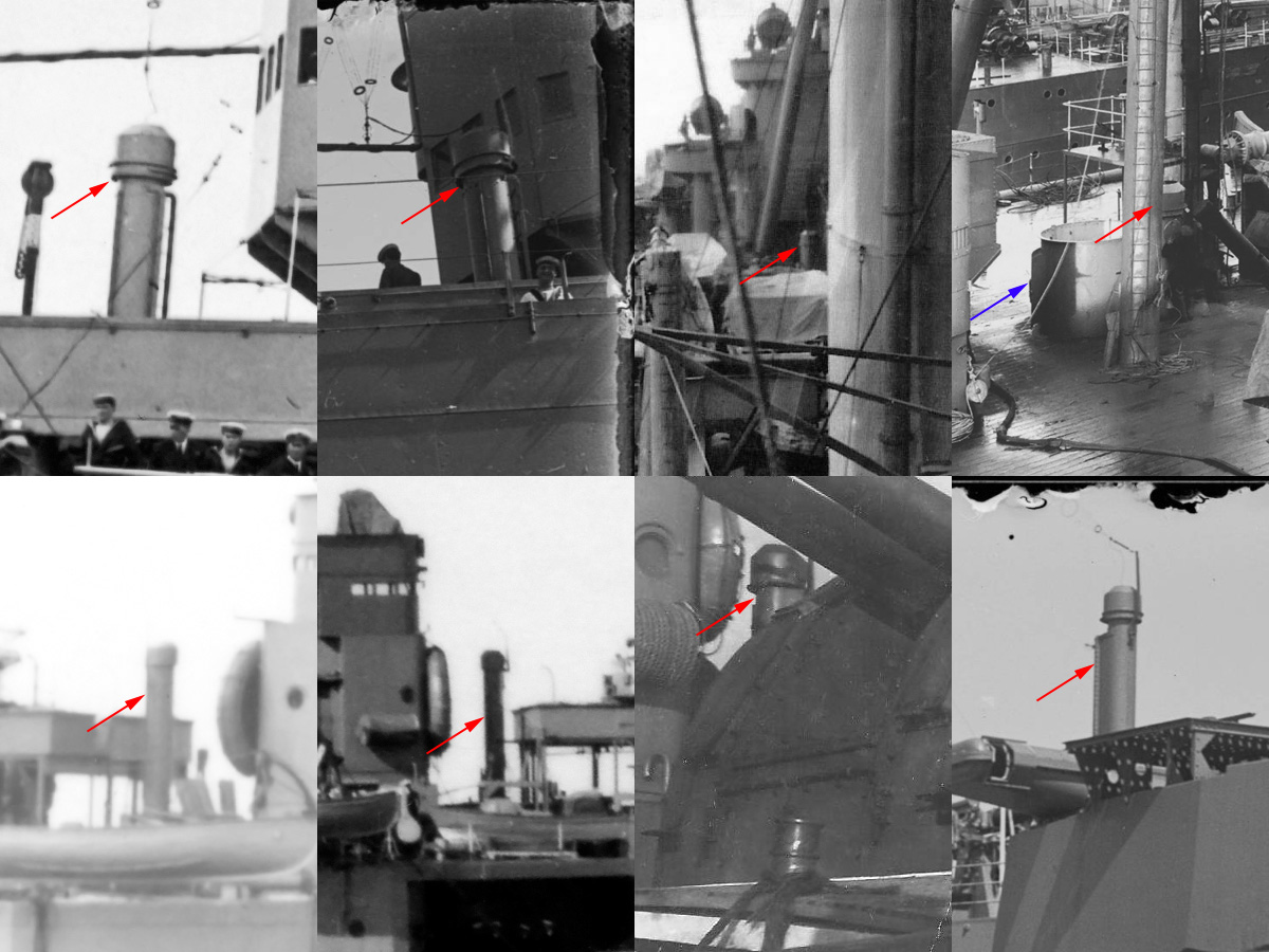
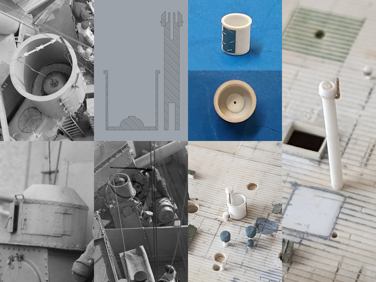
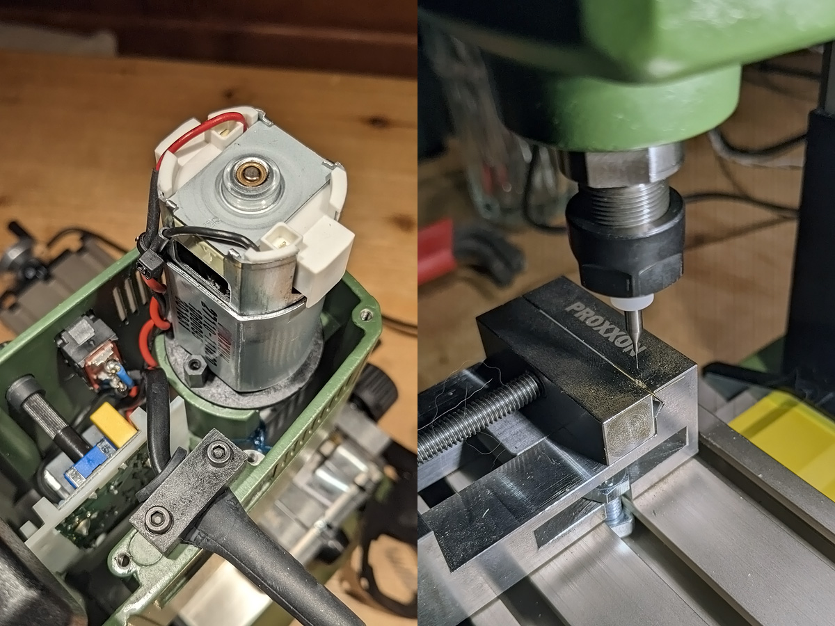
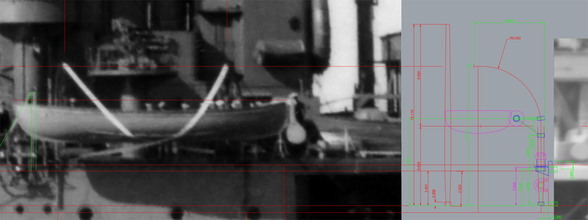
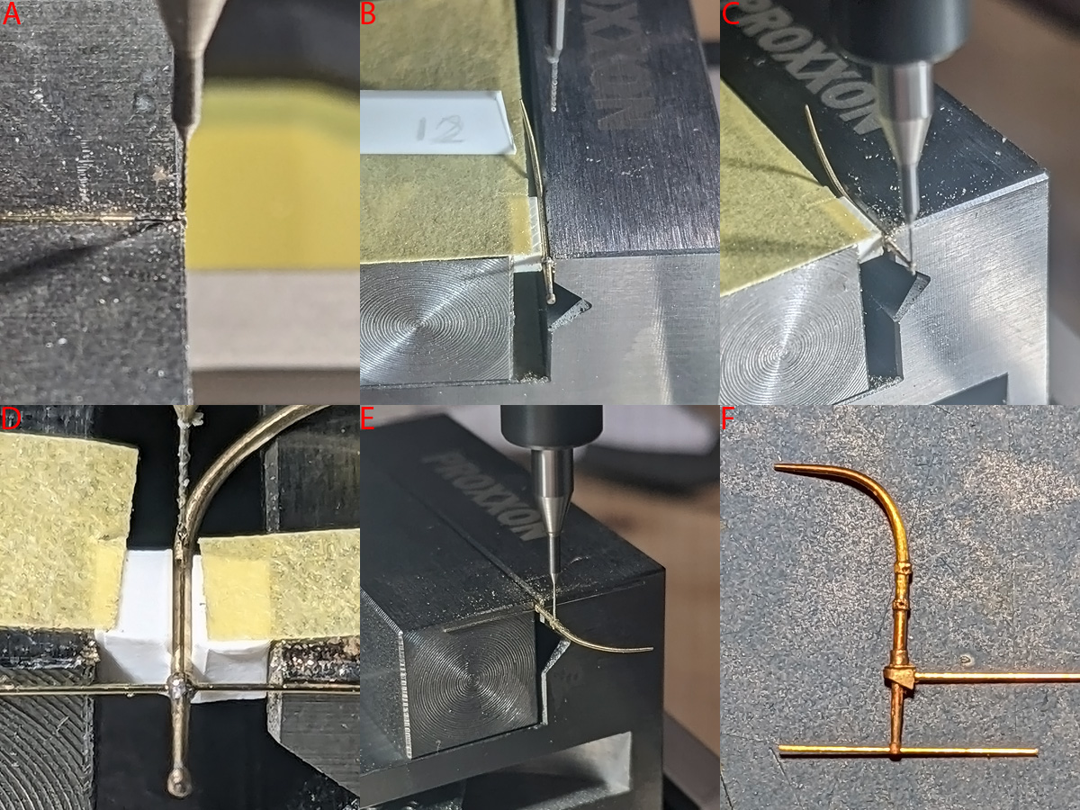
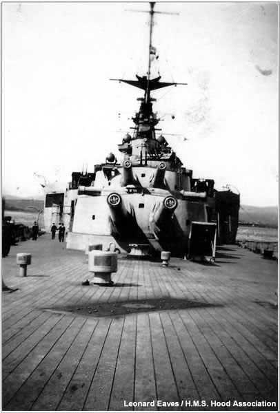
One of the issues that complicates any HMS Hood build is the area below the shelter (or boat) deck; the main deck parts should be fully painted before securing as the region cannot be accessed. The number of photographs of this region is modest and I made post earlier here. The ceiling of the shelterdeck was populated by structural elements, mainly a few larger longitudinal girders A & B). Some transverse girders appear perforated (C); I copied this style to multiple locations while playing with my milling machine. The outer girder appears to be placed where the shelterdeck used the end before it being widened in 1938. The bottom-right image is reproduced with permission from the HMS Hood association and shows the area below the boat deck quite clearly; other images from this 1940-41 album indicate a few minor changes to the model were in order! A few details could be seen on other images: the hammock rails (D) and support stanchions (E) placed below the boat crutches on the boat deck. These pillars have a white centre, covered by a sewn-on canvas gaiter (painted stanchions are also observed on other ships). Now we can also find the ammo lockers for the UP launchers that according to Northcott were stored below decks (4 lockers per launcher, F) . A series of Denton rafts is found (G), a very large vent trunk (H). At (I) a Dan buoy is found stored against the ceiling as identified on the Britmodeler forum; these buoys were used to mark a channel swept of mines. All warships were fitted with mine sweeping gear (paravanes) that was only effective only against contact mines and useless against magnetic, acoustic, or pressure mines, and there’s something counter-intuitive about using HMS Hood as a minesweeper and having her carry danbuoys. But once noticed I started spotting them in more places, see e.g. Jonhston’s & Buxton Battleship Duke of Yok, page 161, with a buoy next to the engine room vent. More on a small model of these buoys in a later post.
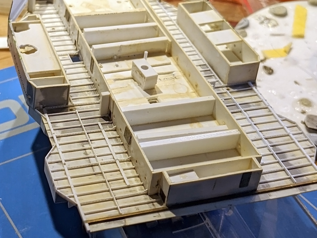
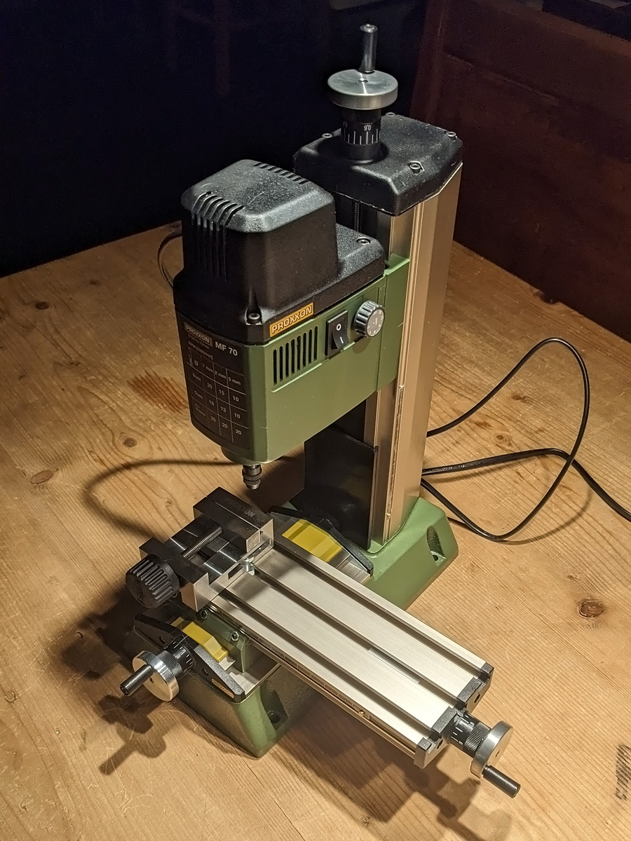
I bought a few original plans of HMS Hood earlier showing the shelterdeck and the structural details; these support beams are spaced 4 ft apart. I previously added some random detail to the ceiling of the shelterdeck when my favourite modelling tool apparently was putty and everything was glued with Uhu plast (bottle with a small needle); I switched to bottle of Plastic Magic and Tamiya (ultra) thin cement last year and this was really a step up in build quality. Some damage was collected during handling so the girders were readded in the form of strips. I had some fun with the milling machine and added a few larger perforated beams. I can only see one of these clearly on one image though but why not. I also changed the angled outline of the deck slightly, letting the angled parts end exactly on a beam end; the original plan set that I have does not seem to follow the outline very well and the model now matches the photographs much better. The position of the support pillars was drilled in earlier; the pillars themselves were made from three Albion-Alloy tubes, so that the centre can be neatly airbrushed white. Unfortunately, the pillars positions were added based on the general arrangements and do not end up exactly below the girders. I cheated a bit and lowered all pillars, the outboard row of pillars end up behind the main longitudinal girder and I added some strip at the ends of the inner row where all pillars should end.
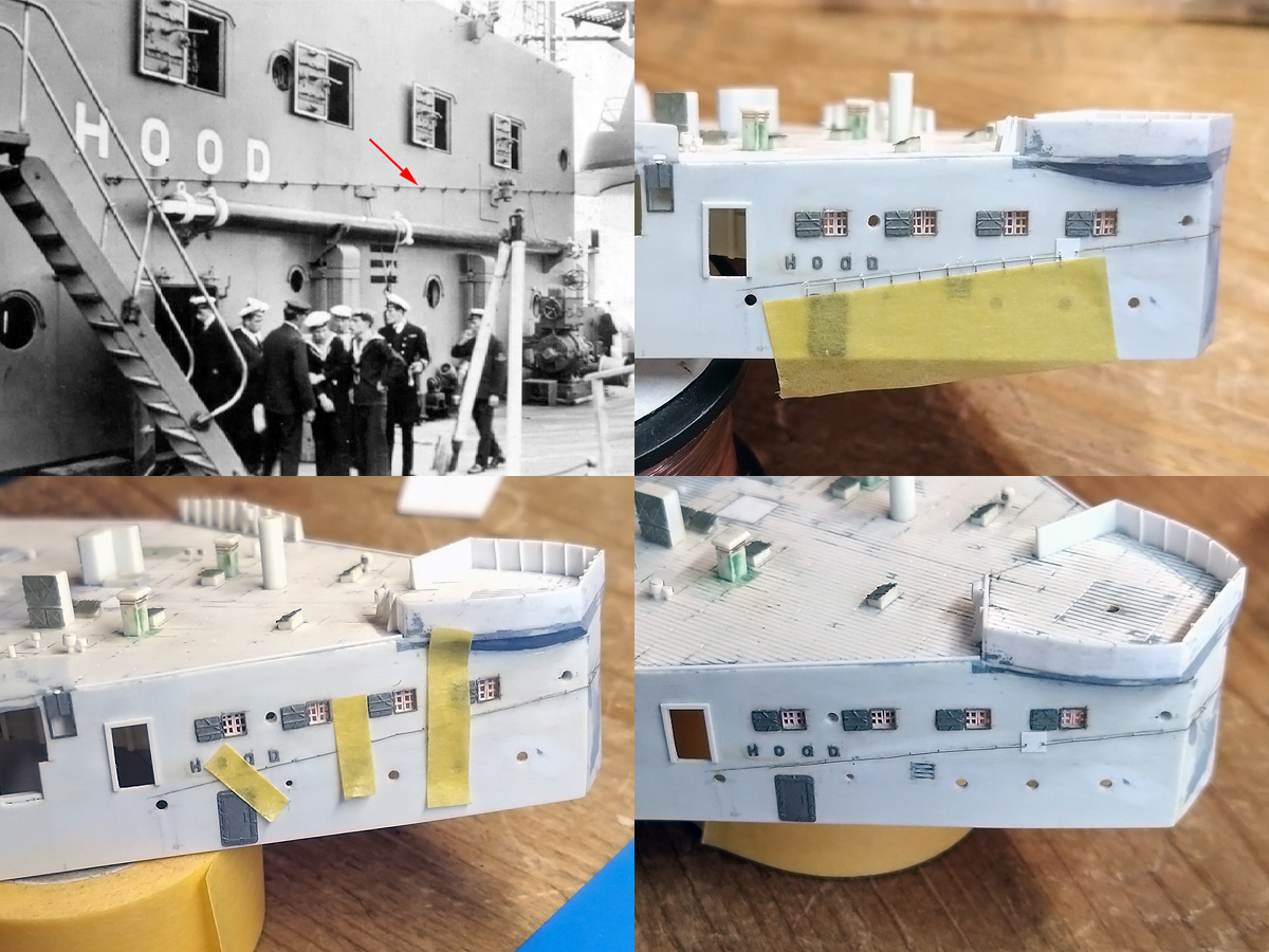
The overall effect is quite nice… (pillar strip apparently not yet added here).
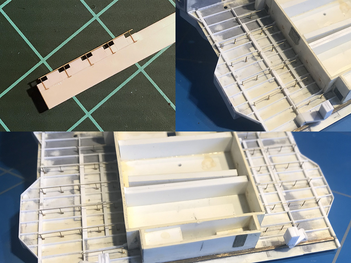
The hammock rails were added next, using a simple alignment tool to glue to etched parts in place. I put the rails right between the girders. If all goes well, none of the support stanchions and hammock rails intersect (did a lot of measuring and drawing to convince myself).
These are very fragile so the part is now much more difficult to handle..
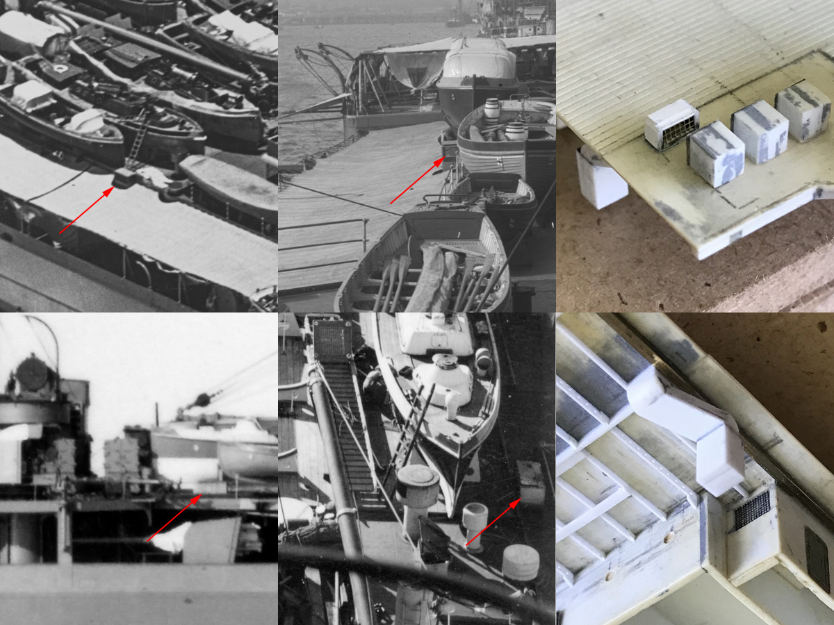
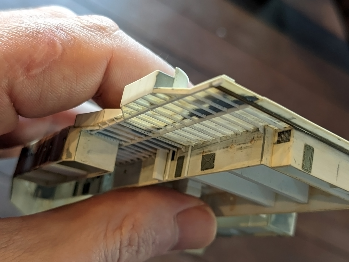
The larger trunk is the the dynamo room vent and appears on the boat deck. It is open on the sides on some images and closed off on most others and copied that style. The trunk didn’t really end up nicely with the position on the main deck on my model. I already had a vent there, but that one was in the as-built configuration: I missed the extension to the boat deck. I gave it a slightly larger sweep to the side than on the original drawings. This was a really tricky part making an angle in the horizontal and to the side, and only after fitting the entire part I could see if it would align well; this took a few attempts. The main deck on the hull took some damage and Ill probably add a very denton rafts to cover it up.